


Introduction
In automated fluid dispensing, dispensing syringes, barrels, and feed tubes are the core consumables bridging the machine and the workpiece. Their structural and material integrity directly determines dispensing consistency. This whitepaper analyzes the applications of industrial dispensing tubes, evaluates how low-quality consumables degrade product reliability, classifies common defects into five core categories, and provides structural troubleshooting matrixes for production lines.
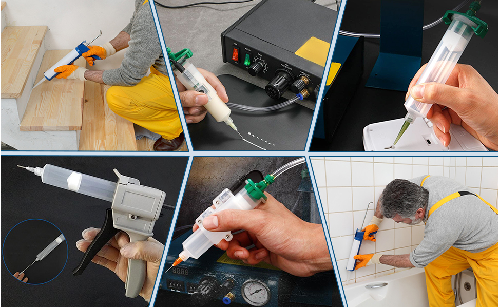
Section 1: Industrial Applications & Quality Impact
1. Primary Application Fields
· Electronics & Semiconductors: Micro-dot sealing and encapsulation for PCBs, camera modules, and TWS earbuds; requires precise delivery of low-viscosity fluids.
· New Energy Vehicle (NEV) & Solar: High-volume delivery of thermal conductive gels and structural bonding adhesives for EV battery packs and photovoltaic modules.
· Medical Equipment Manufacturing: High-purity sealing and bonding of medical sensors and catheters; requires compliance with strict biocompatibility standards.
2. How Substandard Consumables Degrade Product Quality
Using low-quality or counterfeit dispensing tubes damages production efficiency and product reliability across five dimensions:
· Accuracy Loss: Rough internal walls or weak barrel walls cause expansion under pressure. This causes pressure fluctuations, leading to uneven fluid volume, line breaks, or blank dispensing. Ultimately, this results in weak bonding, component detachment, or cold solder joints.
· Contamination Risks: Cheap plastics leach chemical impurities or shed microscopic debris from their inner lining. These particles clog dispensing nozzles and contaminate sensitive components, leading to electrical short circuits or optical degradation.
· Sealing Failures: Defective fittings and connector seals allow fluid leakage or ambient air ingress. This introduces microscopic air pockets into the fluid path, resulting in internal voids after curing that severely compromise waterproof and shock-absorption ratings.
· Chemical & Thermal Instability: Low-grade tubes lack the chemical and thermal resistance required for specialized or aggressive adhesives. They can swell, corrode, or crack mid-process, stopping production and causing curing failures that ruin the product's long-term reliability.
· Operational Efficiency Loss: High consumable failure rates necessitate frequent replacement stoppages. This lowers line utilization, spikes operational downtime, and unnecessarily inflates consumable and labor costs.
Section 2: Classification of Dispensing Defect Phenomenon
Dispensing syringe and tube failures present as either fluid output anomalies (dripping, stringing, bubbles, clogging, uneven volume) or physical consumable failures (air leaks, seal deterioration, material contamination). These directly cause final product defects such as adhesive overflow, starvation, cold joints, and missing dots.
The core failure modes are classified below:
[Dispensing Defects]
├── 1. Fluid Control Anomalies (Dripping, Stringing, Volumetric Variance)
├── 2. Fluid Quality Degradation (Entrapped Voids, Satellite Micro-Droplets)
├── 3. Flow Path Obstruction (Nozzle Clogging, Partial Blockages)
├── 4. Structural & Seal Failures (O-Ring Leakage, Liner Shedding, Burrs)
└── 5. Positional & Morphological Defects (Off-center Dispensing, Poor Enclosure)
1. Fluid Control Anomalies
· Dripping / Oozing: Fluid continues to weep or hang from the nozzle after the valve closes.
· Stringing / Tailing: Elongated, thin adhesive threads stretch out behind the needle during cycle transitions.
· Volumetric Variance & Blanking: Inconsistent dot diameters or complete fluid omission ("blank dispensing") despite the machine executing the cycle.
2. Fluid Quality Degradation
· Entrapped Voids / Bubbles: Air pockets trapped inside the cured matrix (often leading to the "popcorn effect" during downstream thermal cycles).
· Line Discontinuity: Broken or ragged adhesive beads on the substrate.
· Satellite Dots: Micro-droplets splattering around the intended deposit area.
3. Flow Path Obstruction
· Nozzle Clogging: Needle blockages that drastically restrict or completely stop fluid output, typically caused by particulate impurities, cured residue, or fluid cross-contamination.
4. Structural & Seal Failures
· Air/Fluid Leakage: Blow-by or leakage past the piston or adapter joints, often caused by O-ring degradation.
· Adhesive Staining & Particle Shedding: Adhesive clings to rough inner walls, or the liner degrades and sheds plastic particles.
· Workpiece Scratching: Industrial micro-burrs on the needle tip scoring or scratching sensitive substrates.
5. Positional & Morphological Defects
· Off-Center Alignment: Fluid deposits drift or pull away from the intended coordinate path due to unstable pressure.
· Incomplete Enclosure: Failure to achieve a full 360-degree seal around a target component.
· Neighboring Component Contamination: Excess or stray adhesive bleeding into adjacent, non-bonded assemblies.
Section 3: Industrial Troubleshooting Matrix
The root causes of these dispensing defects typically stem from three variables: Improper Parameter Matching, Consumable Wear & Tear, and Equipment/Operational Error.
|
Defect Classification |
Primary Root Causes |
Corrective Actions & Solutions |
|
1. Fluid Control Anomalies (Stringing, Dripping, Volumetric Shifts) |
• Needle inner diameter (ID) is too small.• Dispensing air pressure is too high.• Stand-off height or nozzle speed is incorrect.• Delay in the pneumatic shut-off signal. |
• Increase the needle inner diameter (gauge size).• Reduce the dispensing air pressure.• Calibrate stand-off height; shorten the distance to the substrate.• Calibrate and reduce pneumatic valve response time delay. |
|
2. Fluid Quality Degradation (Bubbles, Voids, Satellite Splatters) |
• Vacuum suckback function is disabled/weak.• Primary feed pressure is too high.• Poor sealing at the tube/adapter connections.• Fluid was not degassed before loading. |
• Turn on or increase the valve's vacuum suckback setting.• Lower the primary fluid feed pressure to stable levels.• Inspect, tighten, or replace loose fluid tube adapters and seals.• Centrifuge or vacuum-degas the fluid syringe before production. |
|
3. Flow Path Obstruction (Nozzle Clogging, Starvation) |
• Incomplete/improper needle cleaning routines.• Micro-impurities or cured skin in the adhesive matrix.• Chemical cross-contamination from incompatible fluids. |
• Set up automated nozzle wiping or regular solvent-cleaning loops.• Purge the fluid path, change the needle tip, and check fluid filtration.• Thoroughly flush the fluid path and valve body before switching adhesives. |
|
4. Structural & Seal Failures (Leakage, Contamination) |
• O-ring/piston seals are worn, aged, or cracked.• Consumable material is degraded by aggressive solvents.• Syringe/tube inner wall is substandard or rough. |
• Immediately replace worn O-rings, pistons, or the entire syringe barrel.• Verify chemical compatibility between the adhesive and the tube material.• Source certified high-precision tubes with polished inner bores. |
|
5. Positional & Morphological Defects (Off-alignment, Spillover) |
• Fluid viscosity changed due to expiration or warm-up failure.• Fluctuating barrel pressure due to tube deformation.• Target substrate surface is contaminated with oils. |
• Allow frozen adhesives to thaw completely to room temperature.• Switch to heavy-duty, rigid-wall syringes that resist swelling.• Clean the substrate surface prior to initiating the dispensing cycle. |
Section 4: Incoming Inspection and Quality Evaluation Framework
To prevent defects before they reach the production line, quality control (QC) and procurement teams must evaluate industrial dispensing tubes across three core dimensions:
1. Visual Appearance and Dimensional Verification
· Surface Condition: The tube wall must be entirely free of bubbles, pinholes, delamination, localized swelling, or unraveled braiding cords. The outer layer must pass strict airtightness standards.
· Dimensional Tolerances: The inner diameter (ID), outer diameter (OD), and tube wall thickness must be uniform. Volumetric and dimensional dimensional variations must be strictly controlled within ±0.5mm to prevent seal failures or low pull-out strength.
· Cross-Sectional Integrity: The internal lining core must be perfectly round. Inner and outer jacket layers must be tightly bonded with zero delamination gaps. Reinforcement layers (e.g., steel wire braiding) must be evenly spaced and clean-cut without loose or frayed wires.
2. Material and Physical Performance Testing
· Environmental Resistance Benchmarks: Samples must undergo high-temperature testing (immersion in boiling water) and industrial oil-immersion tests. Tubes must exhibit zero visible swelling, degradation, or dimensional distortion.
· Structural Strength Verification: Interlayer adhesion must meet industrial specifications, proving that all jacket layers are fused as a single cohesive unit. Bending or flexing the tube must not cause whitening, stress-cracking, or micro-fractures.
· Chemical Compatibility Validation: Material composition must be certified as chemically inert to the specific production adhesives used. This ensures zero risk of solvent corrosion or chemical leaching that could contaminate the fluid.
3. Certifications and Traceability Verification
· Regulatory Compliance: Give procurement preference to manufacturing plants certified under ISO 9001 quality management systems. Specialized applications (e.g., medical, automotive) must possess the corresponding industry-specific entry credentials.
· Third-Party Lab Reports: Review official third-party validation certificates. Confirm that technical specifications for pressure ratings, chemical media resistance, and accelerated thermal aging meet design requirements.
· Industry Track Record: Cross-reference operational feedback from equivalent industrial use cases. Prioritize brands with proven, mature application histories in identical field environments.
Section 5: Production Line Rapid-Screening Checklist
When a line operator sets up a shift, they should perform these four checks immediately:
1. Fluid Readiness: Verify the syringe has been fully degassed and thawed to room temperature to secure stable viscosity.
2. Nozzle Geometry: Check the needle tip under magnification for manufacturing burrs, ensuring the needle gauge matches the fluid type.
3. Pressure Balancing: Balance the drive air pressure against the valve's vacuum suckback. Too little suckback causes dripping; too much suckback draws air into the tube, causing bubble voids and spitting.
4. Seal Auditing: If dripping or line breaks persist despite parameter optimization, immediately replace the dispensing needle or swap out failing O-rings and adapter couplings.